In all figures, channel 1 (yellow) shows the 100 KHz drive signal, while channel 2 (blue) shows the output of the rms-to-dc converter.
Figure 1: This is what we had when the beam went off in late December. The 1/e time constant on the trailing edge is about 15 microseconds, but needed to be 7+-1 microseconds to match the MD. The bleedthru at 200 Khz was only +-few percent. It is an artifact of the rectification of the 100 KHz carrier.
Figure 2: After the two changes listed in hclog 212466, the 1/e time constant has been reduced to about 8 microseconds. The 200 KHz bleedthru increased to about +-12%. This modulation on the otherwise flat top of the pulse reminded me of Bart Simpson's hair style. Like his hair style, this bleedthru is largely cosmetic since the ADCs have a sharp cutoff at 50 KHz. It would be nice though to suppress the 200 KHz so it's easier to compare the MD and BCMs on a scope. But with a passive RC filter one can't beat down 200 KHz without screwing up the time constant again. I found a vendor of passive Chebyshev filters with a really steep cutoff that might do the job.
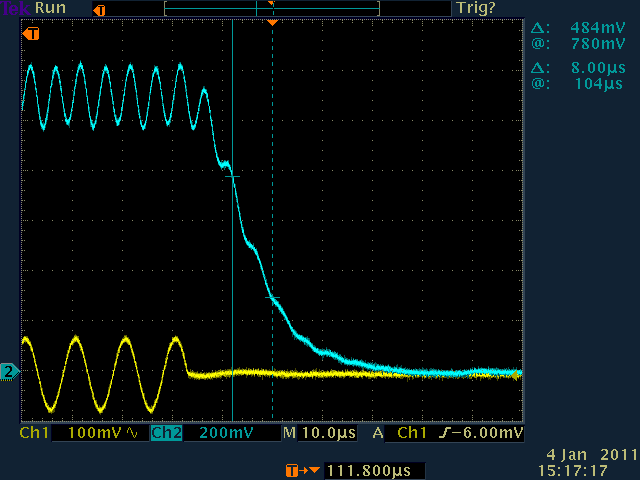
Figure 3: Measurement of the 1/e time constant which is presently about 8 microseconds. It is close to the goal of 7+-1 microseconds needed to match the MD time constant, especially considering my fake pulsed beam isn't shutting down completely. I'll leave it like this until we can check it with real pulsed beam.
notes:
Built two RC filters to try to explore how to clean up the 200 KHz. To keep from increasing our time constant, set f_cutoff conservatively to 145 KHz. The attenuation at 25 KHz is nice and small (1.5%), but the 200 kHz attenuation is only 41%. An RC filter just isn't sharp enough to heavily suppress 200 KHz without significantly attenuating 25 kHz.
Attempted to build a 4-pole RC filter to suppress the 200 KHz while leaving our 25 KHz bandwidth intact. Someone in the electronics group said this would work, but it clearly didn't. Reviewed the transfer function derivation, and realized that the basic assumptions (zero impedance for the source on the input side, and infinite impedance for the measurement device on the output side) are violated as soon as you try to cascade them. The individual RC stages would have to be separated by buffer amps.
The above restriction apparently doesn't apply to inductor-based, commercially available filters which are beyond my ken. I'm getting a quote.
Figure 1: BCM1,2 response end of December

Figure 2: present BCM1,2 response with higher bandwidth

Figure 3: measurement of BCM1,2 time constant