Difference between revisions of "Beam Checkout Procedures"
From HallCWiki
Jump to navigationJump to search| Line 60: | Line 60: | ||
- Locate the hole in the 2D intensity histogram | - Locate the hole in the 2D intensity histogram | ||
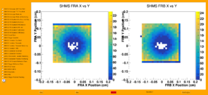
[[File:hallc-carbon-hole.png|thumb]] | [[File:hallc-carbon-hole.png|thumb]] | ||
| − | - Center Beam on Target: | + | - Center Beam on using Carbon-Hole Target: |
- Iterate until the hole is clear, and is centered in the square raster pattern | - Iterate until the hole is clear, and is centered in the square raster pattern | ||
- Adjust beam position | - Adjust beam position | ||
- Re-run the online analzyer on the new file(s) to see the effect of a raster size change and/or beam position change. Make sure changes are logged in the CODA start-run entries! | - Re-run the online analzyer on the new file(s) to see the effect of a raster size change and/or beam position change. Make sure changes are logged in the CODA start-run entries! | ||
- Calibrate raster dimensions against (known, typically 2mm diam.) Carbon Hole diameter by adjusting Raster magnet settings until raster an appropriate size (RC will know). | - Calibrate raster dimensions against (known, typically 2mm diam.) Carbon Hole diameter by adjusting Raster magnet settings until raster an appropriate size (RC will know). | ||
Revision as of 19:11, 29 November 2018
Basic Beamline, Raster, Instrumentation checkout
Initial Raster checks
  Goals
   - Establish beam to be roughly centered in beam pipe by locating it on YAG viewer just upstream of target.
   - Turn on Raster and verify beam profile expands as expected.
 - Beam Current:   Viewer limited (Tune Beam)
 - Target:         Empty, or solid target
 - Raster:         Off; 2mm x 2mm
 Procedure
 - Insert YAG viewer on Hall C superharp girder
   - start with raster off, verify beam spot roughly centered
   - request raster on:  2mm x 2mm
     - watch beam spot on viewer and verify Raster's basic functionality
 - Retract viewer
Harp scans
  Goals
   -Verify operation of Harp scanners w/ beam.
   - Establish acceptable beam profile (nominal 100--500um sigma)
 - Beam Current:   5 uA CW
 - Target:         Empty, or solid target
 - Raster:         Off
 Procedure
   - Verify that the raster is OFF for the harp scans at the target (3H07)
   - Take Harp swipes for all viewers on Hall C beamline
   - verify beam profile (nominal 100--500um sigma) on at least one scanner on Hall C upstream beamline (good to check 3H07A/B)
Target/Beam centering, Raster calibration
  Goals
   - Establish beam position on target.
 - Beam Current:   5--10 uA CW
 - Target:         BeO, Carbon Hole
 Procedure
 - Note:  DAQs should be running and a solid target is in place
   - Online shift crew will proceed with program below.
 - Attempt to view beam on BeO (if available in target ladder)  ** NOT available in current target configuration (2017--2019) **
     - Target:    BeO
     - Current:   5 uA CW
     - Raster:    OFF
   - Target camera: ON
   - Target lamp:   OFF
   - Log camera snapshot of beam spot on BeO
 - Image Carbon Hole target using Raster current pickoffs vs. raw trigger rates in SHMS and/or HMS
     - NOTE: If there are issues with the raster systems, this step can be skipped provided experts are confident that we know where the beam is on target (ie. good BeO snapshot)
     - Target:    Carbon Hole
     - Current:   5 uA CW
     - Raster:    3mm x 3mm
   - Run DAQ on SHMS / HMS
     - Set prescales to ensure DAQ rate is dominated by scintillator triggers (ie. 3/4)
   - Run the online analyzer and look at the 'Fast Raster' panel of the online GUI:
     - Locate the hole in the 2D intensity histogram
   - Center Beam on using Carbon-Hole Target:
     - Iterate until the hole is clear, and is centered in the square raster pattern
       - Adjust beam position
       - Re-run the online analzyer on the new file(s) to see the effect of a raster size change and/or beam position change.  Make sure changes are logged in the CODA start-run entries!
   - Calibrate raster dimensions against (known, typically 2mm diam.) Carbon Hole diameter by adjusting Raster magnet settings until raster an appropriate size (RC will know).
