Horizontal Beam Position, SEM vs. raw ADC. |

Vertical Beam Position, SEM vs. raw ADC. |
In Progress
Calibration of Beam Raster ADC against SEM
Overview
Gen01 Batch Replay Setup
The Gen01 beam was continually rastered across the face of the target. This was done by two complementary systems, the fast raster and the slow raster. The fast raster is a standard Hall C feature, intended to broaden the beam spot rather than to move the beam over the target. It has a correspondingly high cycling rate, about 730 Hz.
Overview The slow raster on the other hand is implemented solely to distribute the heating and ionizing effect of the beam even throughout the target. Ideally, this raster pattern is tuned to achieve a constant areal velocity, coupled linear velocities in two dimensions. Since the target diameter is significant, this raster pattern results in significant beam deflection, large enough to have an impact on the spectrometer reconstruction algorithm (the beam raster position is neccessarily also the scattering point).
To account for this effect, we need to know what the beam position is for each interaction. To this end the Secondary Emissions Monitor has been installed. This device continually determines the beam position using two orthogonal arrays of metal foils strips. The resultant beam position measurement is an absolute determination of the beam position, since the foil location has been surveyed and is well known.
Unfortunately, the SEM is very noisy and produces numerous bad and erroneous values. We can turn to another device to get beam position information: the current driving the raster magnets. Since these magnets are responsible for deflecting the beam in the first place, their current is directly proportional to the beam offset from its nominal position. These data, however, are only relative: to obtain an absolute beam position, we need to know what current corresponds to what deflection and we need to know the nominal (undeflected) beam position.
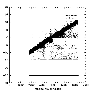
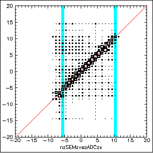
Despite being noisy, the SEM is perfectly suitable to provide this information. The following two plots depict the relationship between the measured SEM beam position (vertical axis) and the raster magnet current (horizontal), as read by an ADC.
|
Horizontal Beam Position, SEM vs. raw ADC. |
Vertical Beam Position, SEM vs. raw ADC. |
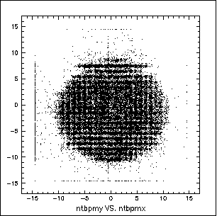
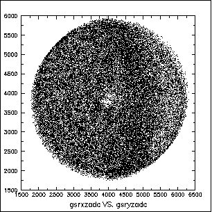
In these plots, the current is given in raw ADC units, the SEM beam position in millimeters. The correlation between the two sets of values, SEM and ADC, is obvious, but so is the noisiness in the SEM. By its design, the SEM can only report beam positions between +15mm and -15mm, with -25mm flagging a bad read. The two saturation levels at +/-15mm and the zero reading are also easy to spot.These plots also clearly indicate that the system is rather noisy, though the source is not identifyable -- it could be contained in either set of variables, SEM or ADC. If we instead plot horizontal versus vertical beam position, seperately for ADC and SEM, this becomes obvious:
2D Beam Position, SEM. |
2D Beam Position, ADC. |
It is obvious that the best solution would be to use the raster current read via the ADC for the beam position. All we need to do is determine the conversion from ADC units to absolute beam position coordinates. We can do this by simply fitting a straight line to each of the SEM vs. ADC plots, obtaining the deflection scale from the slope and the undeflected position from the offset. Note that the zero-deflection ADC value is not at zero, since we need to deflect in a positive and a negative direction.The plots below again compare the SEM value with the ADC current reading, but this time we have applied the conversion from ADC value to beam position (calibrated ADC). Ideally, they both have the same value now, which would put all the data on top of the diagonal, marked in red.
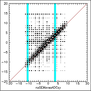
Horizontal Beam Position, SEM vs. calibrated ADC. |
Vertical Beam Position, SEM vs. calibrated ADC. |
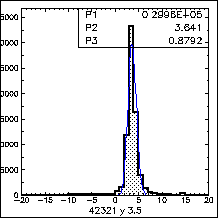
These plots are automatically generated by the replay engine (via CTP) when the runs are analyzed; they are intended to allow a quick verification of the calibration values and The two dimensional histograms shown are defined with 1mm bins in both coordinates, reflecting the SEM construction with 1mm foils and (approximately) of our accuracy requirements.A special script was created to quantify the information contained in these histograms. The presence of the significant noise and the asymmetric distribution of this noise made any simple fitting impossible. Instead, the script looks at each ADC bin seperately, slicing these plots into 1D histograms. Those are then fitted individually and the results averaged, weighed by the width of the Gaussian used to fit the SEM signal for each ADC bin.
Two slices each for horizontal and for vertical raster are shown below. They correspond to the bins shaded in the above 2D histograms for run 42231. The actual fit is overlaid and the resulting parameters are also displayed. The full set of 43 slices (for this particular run) is avaliable here, but be aware that this page will load 43 images...
 |
 |
|
 |
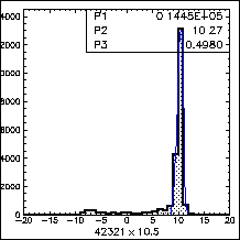 |
Without making specific assumptions about where the beam is located or how accurate the applied conversion is, we cannot eliminate any of the noise prior to fitting. A second pass or a more interactive approach could reasonably utilize such a cleanup, but that effort does not seem warranted. For the run selected for these plots and figures, the script determined the following deviation of the converted ADC values from the actual, fit-determined SEM based beam position:
| x | (vertical) | -0.12 | +/- | 0.13 |
| y | (horizontal) | 0.12 | +/- | 0.18 |
Unfortunately, any discussion of the SEM and the ADC needs to address the issue of coordinate systems. That is due to the multiple systems in use in this context. Here is a list and their definition:
Coordinate Systems SEM:
z is not actually defined (@D system!)
x -- horizontal, left is positive
y -- vertical, up is positiveADC == transport:
z -- along beam
x -- vertical, down is positive
y -- horizontal, left is positiveThis accounts for the matching of SEMx with ADCy and vice versa, as might have been observed in the above plots, as well as the negative slope of the SEMy-ADCx plot. WANT: 1d histogram of good and of bad slice, fit.
The following from Marko while he was at Basel, thus likely to be authoritative:
Inherent SEM Resolution
The intrinsic resolution of the device is limited by the noise of the gated differential integrators. Assuming an integration time equal to 1mm beam travel, tuned thresholds and perfect operating conditions one can achieve a resolution of about 0.25mm according to a Monte Carlo simulation. If the beam hits only one foil during integration time then the resolution is just given by the width of the foil strips (1mm). This was the case for GEn98 operation with fast raster off. Turning the fast raster on increased the probability to hit more than one foil during integration time and interpolation and thus better resolution was more likely.
In the Gen01 case we had a spiral slow raster of 750Hz (which is several times higher than in 98). The fast raster was planned as spiral 24kHz but in the end we used something rectangular of which I do not know the frequencies, but I am sure it was in the kHz domain too. The integration time was 20us. Looking at the slow raster alone one gets a beam travel of 0.9mm during integration time at the maximum radius (1cm). For smaller radii the travel shortens proportionally and the probability to hit only one foil increases.
Assuming a 24 kHz fast raster of 1mm constant radius (lacking the numbers for the "true" fast raster) one gets a beam travel of 3mm, half the circumference of the fast raster circle. So having the fast raster on should allow interpolation and improve the resolution and make it more or less independent of slow raster radius/position.
For all practical purpose I doubt that the resolution is considerably better than 1mm, but in principle you should be able to give a number here by taking a thin slice of magnet current adc and look at the width of the sem distribution ignoring the pathological noise. That might be actually interesting.
My interpretation of this is that in the center of the raster we expect the resolution to be ~1mm, while at the outer edges it might be as good as 0.5mm or better, but 0.25mm seems to be a hard limit.
| frw November, 2002 |