Collimators and Slits for SHMS
From HallCWiki
Contents
Drawings and Survey of Collimator
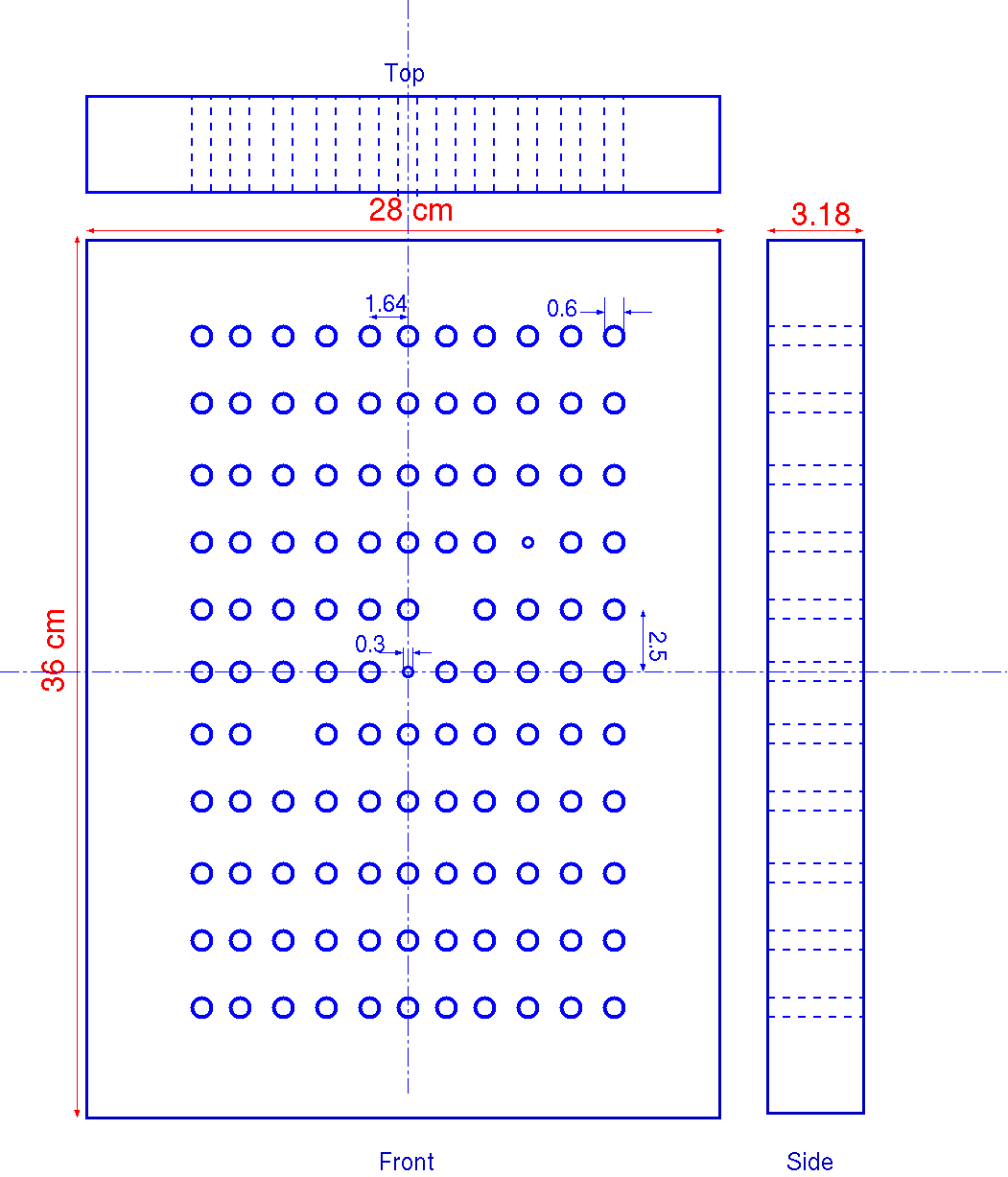
- Drawings of the SHMS sieve and collimator from Bert Metzger April 2014.
- Survey of hole pattern positions in the SHMS sieve April 2014.
New Collimator design
- [Sieve slit placement & design (T. Horn)]
- sieve1, sieve slit plot to compare with Tanja's study above.
- [Collimator study wuth SNAKE]
- Collimator1, Collimator2 and Collimator 3 using the validated mc_shms for 20 cm target at 20 degrees, three collimators are shown, the first is an octagon of 28cm x 14 cm the second is an octagon of 28cm x 18 cm. The first one reduced the acceptance by about 12%, the second one reduces it by less than 1% and the third is an octagon of 23 cm x13 cm which reduced the acceptance by about 24%. In each figure the top left panel shows the x vs y at Q1 entrance, for those events that made it up to the dipole entrance without any collimator on the way. The top right panel shows the x vs y at the collimator for events that make it past the collimator. The bottom left is the overlap of the top two panels and bottom right is overlap of the top right and x vs y at the Q1 entrance for those event that make it to the focal plane without any collimator (including colorimeter feducial cuts).
- New Collimator1, The collimators cannot be placed flush with the Q1 entrance, as in the above figures. The space for the collimator box is at 80 cm from the HB mid-point or about 33 cm from the Q1 entrance. Three sizes of collimators are shown in the figure, 25cm x 17cm, 20cm x 17cm and 18cm x 17cm. These were simulated for a 20 cm target at 20 degree with a -12% to +15% delta cut. The variation of the acceptance with delta is also shown in the figure. There is 8.5% loss of events in the dipole for the 25x17 collimator, 4.6% loss for the 20x17 collimator and a 2.2% loss of events in the dipole with the 18x17 collimator. from this we conclude that the Large collimator will be 25cm x17cm and the small collimator will be 17 cm x17cm octagonal holes.
- Large Collimator Design, Small Collimator Design, Sieve Slit Design, second Sieve Slit Design draft designs of the collimators and sieve slit
- sieve1_a, sieve1_b sieve slit plots for the first sieve slit shown in the draft design
- sieve2_a, sieve2_b sieve slit plots for the first sieve slit shown in the draft design
- sieve1_a compare, sieve1_b compare sieve slit plots for the first sieve slit compared with and without the HB. Red shows the events with HB (same as the 2 plots above) and the blue are events without HB. This demonstrates the influence of the HB on the y, y' and delta (and no effect on the x, x'). It also shows us that just one sieve slit in front of Q1 will not be sufficient for optimizing the reconstruction matrix elements.
- sieve_r1,sieve_r2, Sieve slot plots after adding a tally of materials in a GEM chamber to simulate the effect on the resolution and its possible use along with the sieve slits as a second set of active collimators. The simulations were performed for spectrometer momentum of 2 GeV/c and angle of 20 degrees.
| Material | Amount | rad length (cm) | % of rad length |
|---|---|---|---|
| Mylar | 10 micron | 28.7 cm | 0.004 |
| Copper | 24 micron | 1.43 cm | 0.17 |
| Kapton | 200 micron | 28.6 cm | 0.07 |
| G10 | 3 mm | 19.4 cm | 1.55 |
| Nomex | 4 mm | 1312.5 cm | 0.03 |
| Glue | 60 micron | 20.0 cm | 0.03 |
| CO2 | 9 mm | 1831 cm | 0.05 |
Meeting about collimator design on March 13, 2013
- Presentation by Dipangkar Dutta on passive and active collimators.
- Two slides by Mark Jones. First slide has for electrons which make it to the SHMS focal plane plots of the vertical versus horizontal position at 80cm from the target for different SHMS angles and target lengths. The second slide has table of resolutions for Xptar,Yptar, delta and Ytar for various combinations of entrance windows to the SHMS.