The features of the data acquisition electronics from the output of PMT's, through trigger and inputs, to the Fastbus modules, are discussed in this section. The philosophy of the Hall C fast electronics is to bring all the raw phototube signals into the counting house where the trigger and digitization are. The only exceptions to this are the TDC's for all of the wire chambers. Since the wire chambers use multi-hit TDC's in a common stop mode, the common signal may arrive at the TDC modules long after the individual inputs.
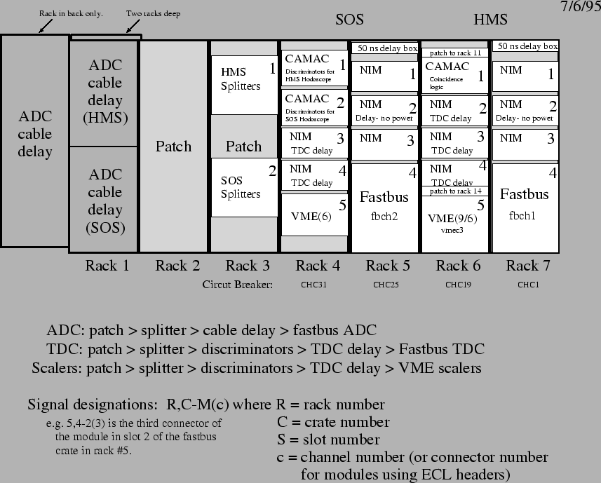
The readout electronics for all Hall C detector systems (except the drift chambers) are located in Counting House C (Bldg 97, room 101A). There are seven primary racks in this counting house (Figure 2.36).
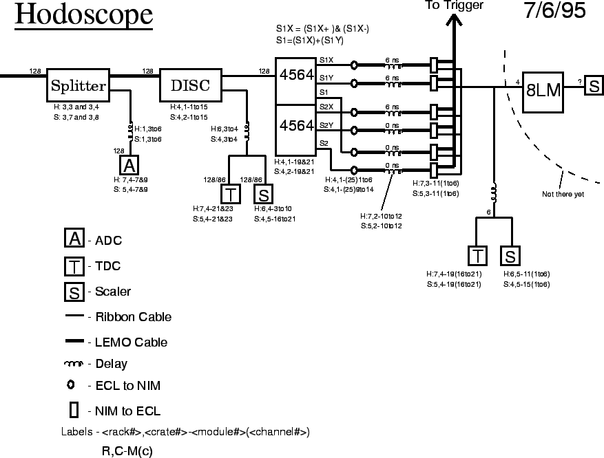
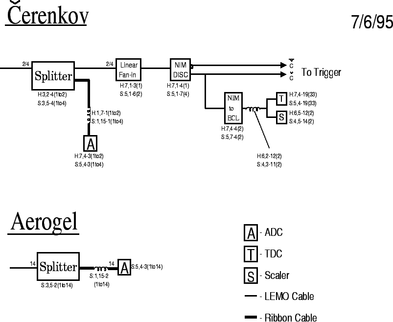
Two of these contain the patch panels where the signals from the hall are brought to the counting house. The others contain the fast electronics used to form the trigger and to readout the data. There are additional racks in the counting house which contain electronics related to the beam current monitors and beam rastering system. Figures 2.37- 2.41 show the trigger electronics, arranged by detector system. Figure 2.42 depicts the layout of the HMS trigger electronics.